
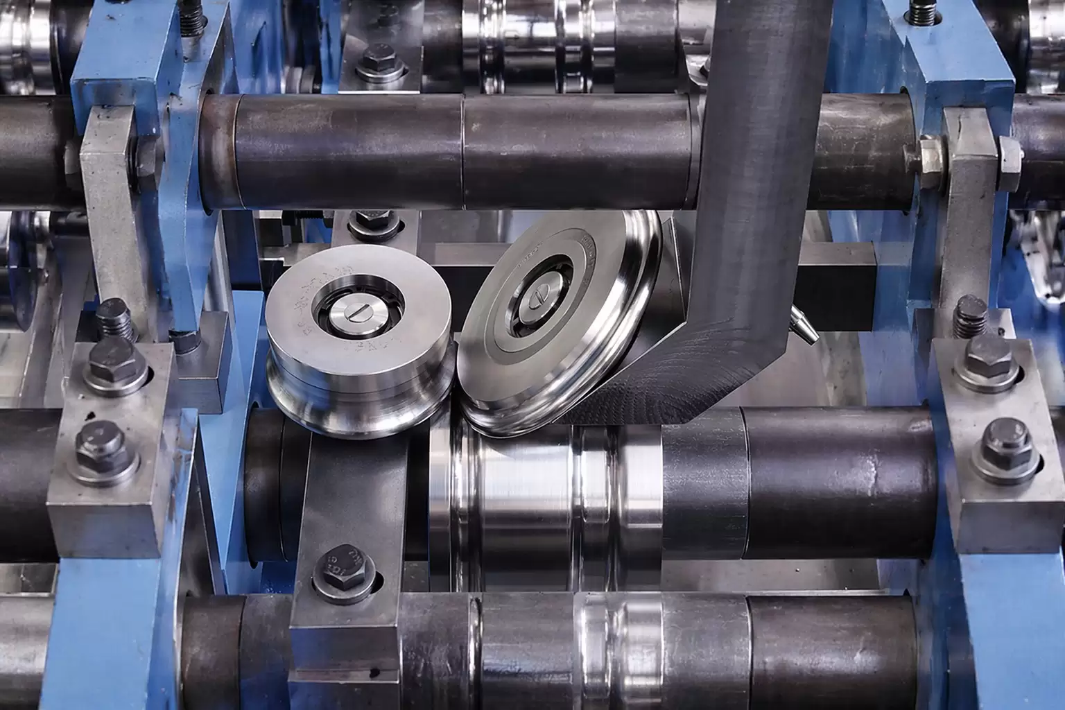
Most roll forming machines are custom — not in the sense that each machine is built from scratch, but in the sense that the roller tooling, the number of forming stations, the punching die, and the cutoff system are all configured specifically for the profile you intend to produce.
Understanding how customization works — what is standard, what is configurable, and what is genuinely bespoke — gives you the knowledge to specify the right machine and avoid paying for customization you do not need, or under-specifying and getting a machine that cannot produce your profile.
What Is Actually Custom in a Roll Forming Machine?
A roll forming machine has two distinct layers:
Standard components (machine body): The decoiler, leveling unit, machine frame, drive system, PLC control cabinet, cutoff press, and run-out table are standard engineering products that do not change significantly between profiles. The same machine frame can be fitted with tooling for a cable tray, a solar channel, or a strut channel — the frame is not profile-specific.
Custom components (tooling): The roller tooling sets — the actual forming rollers and their mounting configuration — are manufactured specifically for your profile. The punch die (if the machine punches holes) is manufactured specifically for your hole pattern. These are the custom elements that determine what profile the machine produces.
This distinction matters because: machine body lead time is typically 20–30 days; custom tooling lead time is 30–50 days. The overall manufacturing time is dominated by tooling, not by the machine body.
Step 1: Provide a Cross-Section Drawing
The starting point for any custom roll forming machine is a cross-section drawing — a 2D drawing showing the exact geometry of the profile you want to produce.
What the drawing must include:
- All dimensions of the cross-section (width, depth, flange length, lip return, bend radii)
- Dimensional tolerances on every critical dimension (e.g., overall width: 41 ±0.3 mm)
- Material specification (steel grade, thickness, coating)
- Any hole or slot pattern (position, dimensions, pitch)
- Required profile length and length tolerance
- Applicable standard (if any — e.g., EN 10162, ASTM A1011)
What happens if you provide a sample instead of a drawing: The tooling manufacturer will reverse-engineer the profile from the sample. This works — but there is risk. Tolerances are assumed, not specified. If the reverse-engineered dimensions differ from your expectation, you have no contractual basis for tooling rework at the supplier's cost.
Recommendation: Always provide a dimensioned drawing, even if you derive it from a physical sample. It takes one day with a set of digital calipers and basic CAD software, and it eliminates the most common cause of post-delivery disputes.
Step 2: Forming Sequence Design (Flower Pattern)
Once the tooling manufacturer has your cross-section drawing, they design the forming sequence — the progressive series of partial cross-sections that each roller station must produce to arrive at the final profile without causing material defects.
This design is called the flower pattern (named for how the overlapping cross-section stages look when drawn together). It determines:
- How many roller stations are needed
- The angle progression per station (typically 5–10° per station for steel; 3–5° for aluminum)
- Which bends are formed first (typically flanges before web, outside-in)
- Where in the sequence holes should be punched (almost always before forming)
Software-assisted design: Reputable tooling manufacturers use roll forming simulation software (COPRA RF, Profil, or equivalent) to design the flower pattern. The software models the material deformation at each station and predicts potential problem areas (longitudinal strain, bow, twist) before any tooling is cut. This is not a luxury — it is the most reliable way to get the forming sequence right the first time and avoid expensive tooling rework.
Ask your supplier: "Do you use simulation software for forming sequence design?" A yes answer with specific software names is a positive signal. A vague answer about "experienced engineers" is a risk factor.
Step 3: Roller Tooling Manufacture
Once the forming sequence is finalized, the roller tooling is CNC-machined. This is the longest lead-time step.
Tooling manufacture process:
- Raw stock machined to rough roller blank dimensions
- Profile turned to forming geometry on CNC lathe
- Heat treatment: quench and temper to target hardness (Cr12MoV to HRC 58–62)
- Finish grinding to final profile and surface finish
- Quality inspection: dimensional check against design drawing
Lead time: 25–40 days for a complete tooling set (all stations).
Quality checkpoint: Request the tooling dimensional inspection report before the tooling is assembled into the machine. This documents that each roller was manufactured to the design drawing — creating a quality record for the contract.
Step 4: Punch Die Customization (If Required)
If your profile has a punched hole or slot pattern, the punch die is manufactured to your specific requirements:
What the punch die includes:
- Upper punch (the male element that pushes through the material)
- Lower die (the female element with the clearance hole)
- Stripper plate (holds material flat during punching; prevents material from lifting with the punch on the return stroke)
- Die shoe (holds upper and lower elements in precise alignment)
Die customization parameters:
- Hole shape and dimensions (round, rectangular, slotted, teardrop, butterfly)
- Hole pitch (distance between consecutive holes)
- Multiple hole patterns in one die stroke (e.g., two holes punched simultaneously)
- Punch and die material: SKD11 or D2 tool steel, hardened to HRC 60–62
Lead time: 15–25 days for standard die configurations; 25–40 days for complex multi-hole patterns.
Step 5: Machine Assembly and Factory Acceptance Test
Once the machine body is complete and tooling is manufactured, the machine is assembled and test-run at the factory.
Factory acceptance test for a custom profile:
- Load the specified material (your coil grade and thickness)
- Run 100–200 meters of profile through the machine
- Measure the profile cross-section dimensions at multiple points
- If holes are required: measure hole position accuracy across 20+ pieces
- Measure cut length accuracy across 10+ pieces
- Document all measurements against your specification tolerances
- If any dimension is outside tolerance: adjust tooling and re-run
Key contractual point: The FAT must be conducted with your specified material — not the supplier's generic test coil. Different material grades and thicknesses produce different springback behavior. A machine that meets tolerance with one material may not meet tolerance with another.
Common Customization Scenarios
Scenario 1: Standard profile, standard machine You need a 41×41 mm strut channel with standard slot pattern. This is a well-established profile — many suppliers have existing tooling designs and can manufacture the tooling set in 20–25 days, reducing overall lead time.
Scenario 2: Modified standard profile You need a 50×50 mm strut channel (non-standard width). The forming sequence design is similar to 41×41, but all tooling must be custom-machined. Lead time: 35–45 days.
Scenario 3: Completely custom profile You have a proprietary profile design — perhaps a unique solar mounting rail or a custom racking upright specific to your system. Full forming sequence design from scratch, complete tooling manufacture, and extended FAT. Lead time: 60–90 days. Expect one or two rounds of tooling adjustment at the FAT stage.
Scenario 4: Multi-profile machine with quick-change tooling You need to produce three different profiles on one machine with fast changeover between them. The machine is configured with a raft tooling system — all stations for each profile are mounted on a common base plate (raft), and changeover involves sliding out one raft and sliding in another, typically in under 30 minutes.
What to Include in the Purchase Contract
For a custom roll forming machine, the purchase contract should include:
- Complete cross-section drawing with tolerances (attached as exhibit)
- Hole pattern drawing with dimensions and pitch tolerance
- Material specification for both forming and FAT
- FAT acceptance criteria (list of dimensions and their tolerances)
- Tooling dimensional inspection report (provided before machine assembly)
- Delivery date with penalty clause
- Warranty terms for tooling manufacturing defects
- Confirmation that PLC program will be provided unlocked
- On-site commissioning scope and duration
Conclusion
Customizing a roll forming machine is primarily about customizing the tooling — the machine body is a standard platform. The quality of the customization depends on the forming sequence design methodology (simulation software vs. experience), the tooling material and heat treatment specification, and the rigor of the factory acceptance test.
Give your supplier a complete, dimensioned drawing. Confirm they use simulation software. Require tooling inspection reports. Insist on a proper FAT with your material. These four steps are the difference between a custom machine that produces your profile correctly from the first shift and one that requires months of adjustment before it performs.
Contact our engineering team with your profile drawing. We will review it, provide a forming sequence assessment, and give you a transparent quote with tooling specifications and FAT criteria.
Related Articles:
